
This memo aims at understand the internals of RDMA, and especially what is takes to create an “RDMA-compliant NIC” that interconnects with a PCIe subsystem, such as the 200Gb connectX-7 integrated with the DGX Spark (picture on the right) .
RDMA as a “client server” protocol Link to heading
Let’s start this memo with an overview of RDMA as a protocol.
RDMA Setup Link to heading
When setting up the RDMA data channels, the memory buffers need to be registered with the network card before they can be used. The registration process consits of the following steps:
- Pin memory so that it cannot be swapped by the Operating System.
- Store the address translation information in the NIC.
- Set permissions for the memory region.
- Create a remote+local keys,used by the NIC when executing the RDMA verbs.
RDMA Queue Pairs Link to heading
RDMA communication is based on a set of three queues
SQ: Send QueueRQ: Receive QueueCQ: Completion Queue
The RDMA Queue Pair, or QP refers to the Send Queue + Receive Queue.
RDMA Work Queue Elements Link to heading
Applications issue a job using work request, also refered to as work queue element (WQE).
A work request is a small struct with a pointer to a buffer:
- In a send queue – it’s a pointer to a message to be sent.
- In a receive queue – it’s shows where an incoming message should be placed.
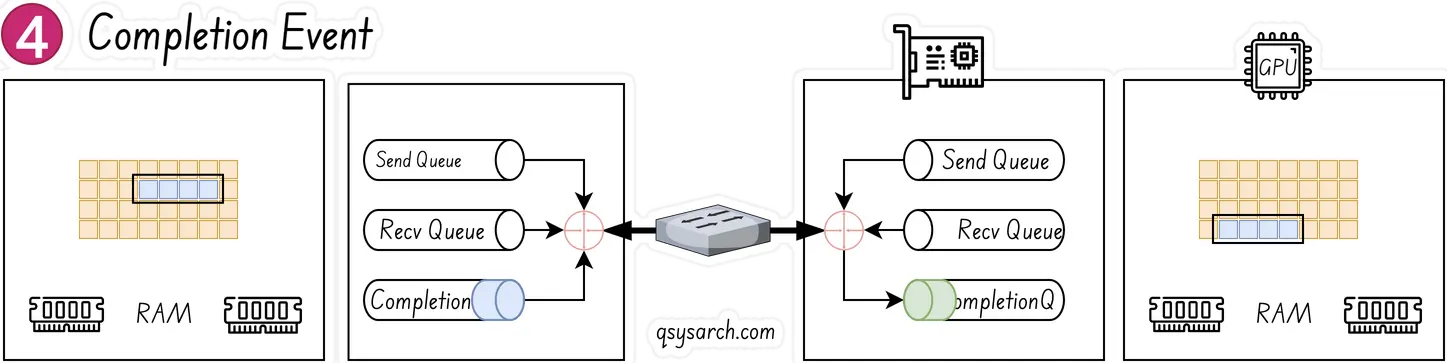
Once a work request has been completed, the adapter creates a completion queue element and enqueues it in the completion queue
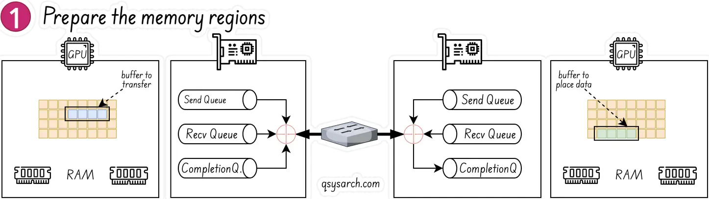
Simple RDMA Write example Link to heading
Sender (left) and receiver (right) entities have created their Queue Pairs and Completion Queues, as well as registered a regions in memory for RDMA to take place. The sending entity identifies a buffer that it will want to move to receiving entity. The receiving entity has an empty buffer allocated for the data to be placed.
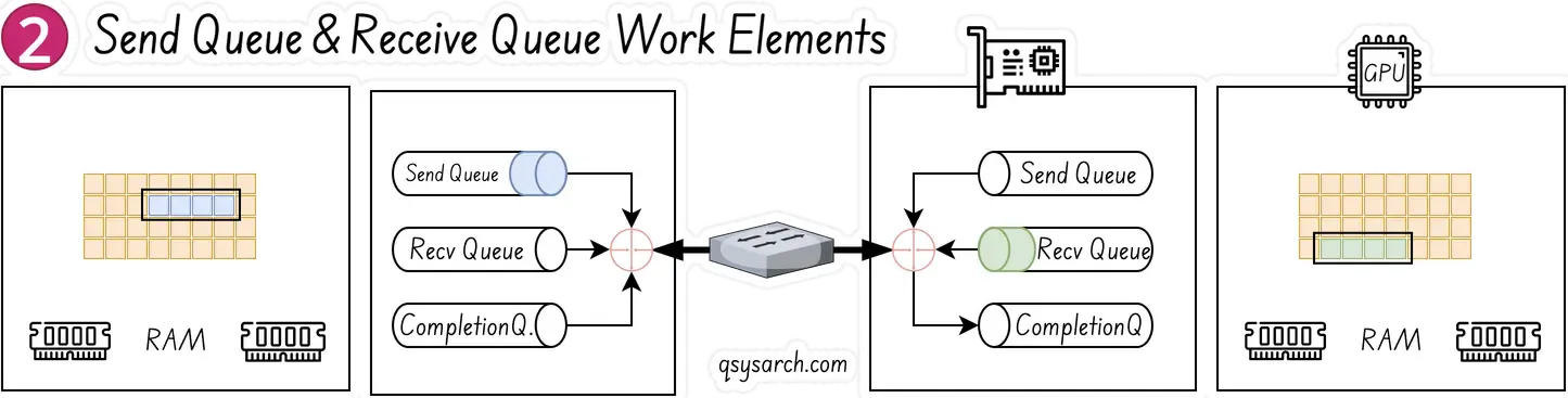
The receiving entity on the right creates a work queue element WQE WOOKIE and places in on the receive queue. This WQE contains a pointer to the memory buffer where the data will be placed. The sending entity on the left also creates a WQE which points to the buffer in it’s memory that will be transmitted.
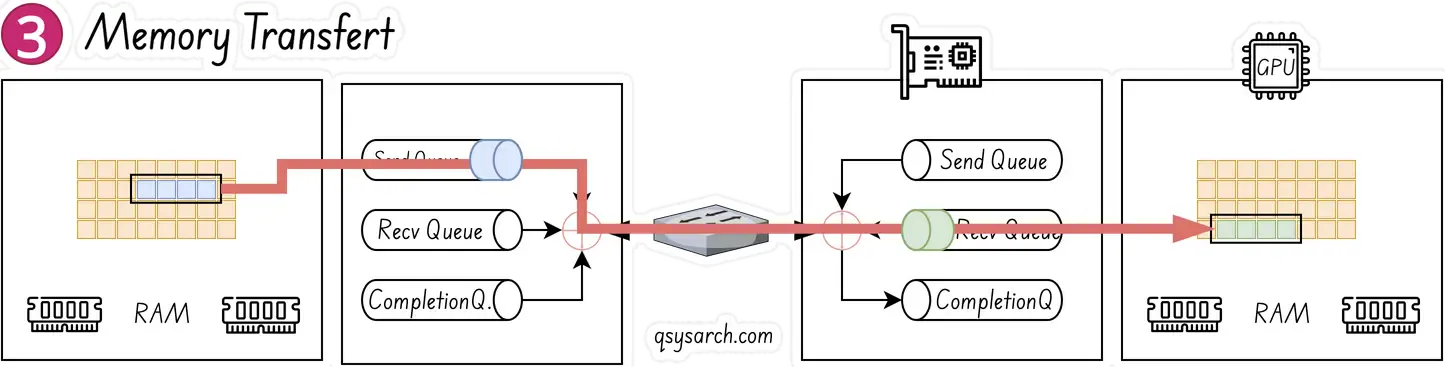
The NIC (understood as the RDMA-complient HW NIC, aka RNIC) is constantly polling and looking for WQE’s on the send queue - this is done without the GPU and CPU to be involed, the polling is only impacting the RNIC. Once a WQE is pushed by the CPU, the RNIC consume it on the sending entity, and begin streaming the data from the memory region to receiving entity. When data begins arriving at receiving entity, the RNIC will consume the WQE in the receive queue to learn where it should place the data.
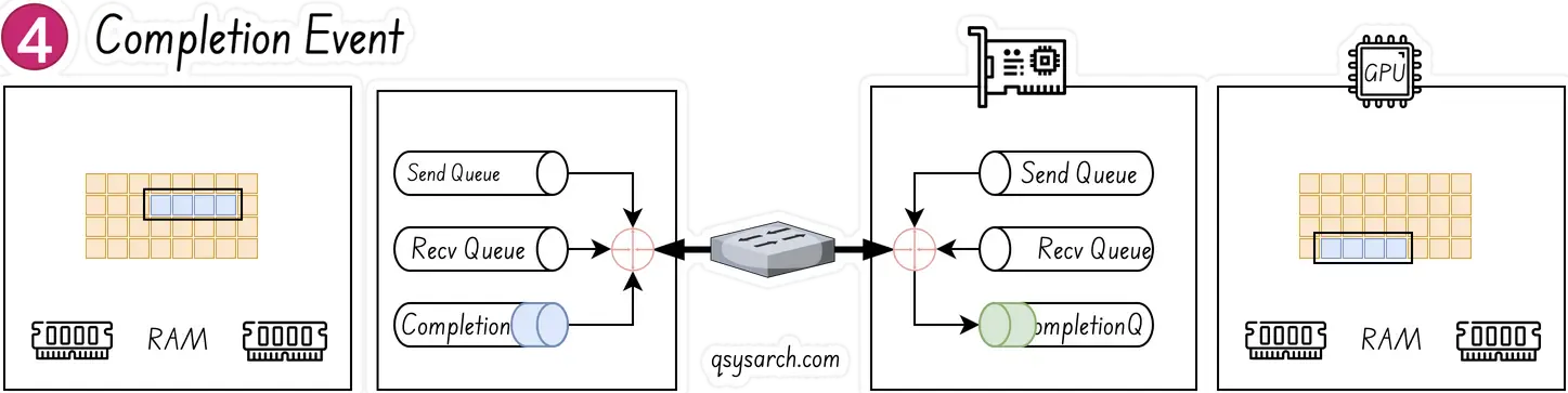
As the last step, when the data movement is complete, the RNIC creates a completion event CQE “COOKIE”, which is placed in the Completion Queue. The event indicates that the transaction has completed. For every WQE consumed a CQE is generated.
RDMA Read and Write Link to heading
It is important to notice that only the sender side is active; the receiver is passive; The passive side issues no operation, uses no CPU cycles, gets no indication that a “read” or a “write” happened.
To issue an RDMA read or a write, the work request must include:
- the remote side’s virtual memory address
- the remote side’s memory registration key
Meaning that the active side must obtain the passive side’s address and key beforehand.
RDMA from a network packet perspective Link to heading
This part is based on the excellent work from Toni Pasanen’s Network Times
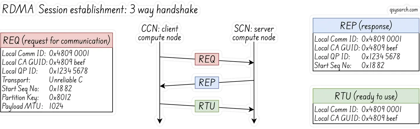
RDMA Session establishment Link to heading
The application on the client compute node (aka CCN) starts the connection establishment by sending a Request for Communication (REQ) message to the application on the server compute node (SCN).
The REQ message includes a mean to identify the physical RNIC and the port:
- Local Communication Identifier (
LID) and Global Unique Identifier for the Channel Adapter (Local CA GUID). The Local CA GUID identifies the RNIC, while the Local Communication ID identifies the port on the NIC.
The REQ message also contains all the meta information about the Queue Pairs.
- Local QP number (0x1234 5678)
- QP service type (Unrealiable Connection)
- starting Packet Sequence Number (PSN: 0x1882)
- Partition Key value (0x8012)
- payload size (1024).
The REP message acknoledges the QP meta data. And finally, the client sends back a Ready to Use (RTU) message, to confirm to the server that the QP is now established. After the session is established, the application on the CCN can start the RDMA Write process.

Terminology:
- CCN: client compute node
- SCN: server compute node
- PD: Protection Domain
- L_Key, R_Key: local and remote keys
- QP: Queue Pair (QP) = Send Queue + Receive Queue.
- CQ: Completion Queue
- RC: Reliable Connection
- UD: Unreliable Datagram
- REQ: CCN sends Local ID, QP number, P_Key, and PSN.
- Reply: SCN responds with IDs, QP info, and PSN.
- RTU: Ready to Use: CCN confirms connection.
- WR: Work Request
RDMA Work Request Message Link to heading
To be completed later - there is nothing outstanding about the WR messages worth mentionning here - if you want more details, check Toni Pasanen’s Network Times and the InfiniBand Transport Protocol
RDMA from a network transfert perspective Link to heading
RDMA Unrealiable connections Link to heading
RDMA UC (Unreliable Connected) does not perform retransmission; instead, it relies on the application to manage reliability and handle lost packets, as UC is a connectionless, unreliable datagram service. The network interface card (NIC) drops packets without attempting retransmission, and the application is responsible for tracking and re-requesting missing data. This is in contrast to reliable connection (RC) QPs, where the network hardware handles retransmissions. So, how does an RDMA UC application knows if a packet is lost?
- Application-level packet loss detection
Packet Sequence Numbers (PSN): The application assigns a unique, sequential number to each packet it sends. The receiver keeps track of these sequence numbers. A gap in the sequence numbers indicates that one or more packets have been lost.
Timeouts: The application-level protocol can implement a timeout mechanism. If a response or an acknowledgment is not received within a certain period, the application assumes the packet was lost and initiates a retransmission.
- Application-level packet loss recovery

- If the receiver detects a lost packet in the sequence, it needs to inform the sender to retransmit this packet. And if the packet used to inform the sender is also lost, then it can end up in pretty complex situations.
- Timeout: The sender expects the receive to acknowledge the packets that hqave been received. If not, the sender proactively resends the packet that has not yet been acknowledged.
Do we always need to build a separate reliability module on top of RDMA QP? Not necessarily. In some situations, it is acceptable to treat a lost packet as a reason to mark the entire session as failed, rather than just resend the missing packet. This approach works because the underlying network is usually reliable enough to provide extremely high reliability, such as only one error in a trillion packets.
Prioritiy Flow Control (PFC) & Explicit Congestion Notification (ECN) Link to heading
RDMA UC does not inherently know if a packet is lost because it’s an unreliable protocol, so packet loss is handled by the application or a higher layer. The “lossless” guarantee in RDMA is achieved through underlying network technologies like Priority Flow Control (PFC) and Explicit Congestion Notification (ECN), which prevent packet drops in the first place.
This protocol encapsulates the RDMA data segment into the UDP data segment, adds the UDP header, then the IP header, and finally the Ethernet header, which is a three-layer data packet. It can be classified by using the PCP field in the Ethernet VLAN or the DSCP field in the IP header.
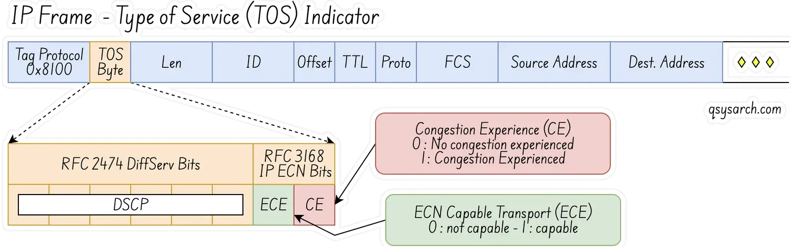
In simple terms, in the case of a Layer 2 network, PFC uses the PCP bit in the VLAN to distinguish data flows. In the case of a Layer 3 network, PFC can use both PCP and DSCP, so that different data flows can enjoy independent flow control. Currently, most data centers use Layer 3 networks, so using DSCP is more advantageous than PCP.
RDMA from a PCIe perspective Link to heading
 The PCIe analysis is based on the excellent paper: SmartIO: Zero-overhead Device Sharing through PCIe Networking from Dolphin.
PCIe Base Address Registers Link to heading
The defining feature of PCIe is that devices are mapped into the same address space as the CPU and system memory, as depicted with the figure on the right. Because this mapping exists, a CPU can read and write to device memory the same way it would access system memory. This is often referred to as memory-mapped I/O (MMIO).
At initialization time, when the system checks the PCIe tree, a memory address range is reserved (by the BIOS or kernel) for each device’s memory regions. This reserved address is then written to the device’s Base Address Registers (BARs). A device can have up to six BARs.
PCIe interrupts (MSI) Link to heading
PCIe uses message-signaled interrupts (MSI) instead of physical interrupt lines. Devices that support MSI send a memory write to the CPU, using a specific address and payload given by the system. The CPU reads this memory write and uses the information to raise an interrupt.
MSI-X is an extension of MSI that allows up to 2048 different interrupt vectors. One advantage is that an MSI-X interrupt can target a specific CPU core in multi-core systems. Also, different MSI-X vectors can signal different types of events.
ConnectX-8 Optimized Design Link to heading
[1] GPU-to-GPU across two CPU sockets: In the traditional design this path may encounter host CPU and inter-socket bottlenecks, limiting to 25 GB/s or less based on the inter CPU link utilization. In contrast, the optimized CX8-based design enables up to 50 GB/s per GPU of IO bandwidth for all inter-GPU communication within the cluster, as NCCL routes all traffic directly through the network.
[2] GPU-to-NIC communication: The optimized architecture provides each GPU with 50 GB/s of bandwidth in a 2:1 GPU-to-NIC configuration, regardless of whether the GPU or host system support PCIe Gen5 or Gen6.
[3] GPU-to-GPU through the same PCIe switch: Systems equipped with PCIe Gen6 benefit from double the bandwidth compared to Gen5, significantly accelerating peer-to-peer GPU transfers over the same PCIe switch.
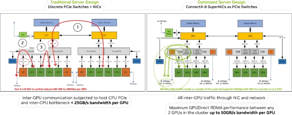
Reference: NVIDIA ConnectX-8 SuperNICs Platform Architecture
RDMA from a Programmatic API perspective Link to heading
This section is based on Netdev 0x16 RDMA tutorial.
Setup Link to heading
Create required objects including PD and CQ
struct ibv_pd *pd = ibv_alloc_pd(verbs_context);
if (!pd) { /* error handling… */ }

struct ibv_cq_init_attr_ex cq_attr = {
    .cqe = num_entries, cq_context = my_context, … };
struct ibv_cq_ex *cq = ibv_create_cq_ex(verbs_context, &cq_attr);
if (!cq) { /* error handling… */ }
Register memory Link to heading
Allocate a buffer to hold data and register it with libibverbs:
void *buf = malloc(BUF_SIZE);
struct ibv_mr *mr = ibv_reg_mr(pd, buf, BUF_SIZE, IBV_ACCESS_LOCAL_WRITE);
Connection establishment with librdmacm Link to heading
Sockets-like, with an asynchronous event-driven interface. (Not strictly required, but provides an abstraction that covers multiple transports) First create an “event channel”:
struct rdma_event_channel *channel;
channel = rdma_create_event_channel();
if (!channel) { /* error handling… */ }
Both sides resolve server address:
struct rdma_addrinfo hints, *rai;
memset(&hints, 0, sizeof hints);
hints.ai_flags = RAI_PASSIVE;
hints.ai_port_space = RDMA_PS_TCP;
err = rdma_getaddrinfo(server_addr, port, &hints, &rai)
Passive side (SCN) creates and binds a listen “ID” and listens:
struct rdma_cm_id *listen_id;
err = rdma_create_id(channel, &listen_id, myctx, RDMA_PS_TCP);
err = rdma_bind_addr(listen_id, rai->ai_src_addr);
err = rdma_listen(listen_id, 0);
/* events will be generated for incoming connection requests */
Active side creates ID and resolves address of server:
struct rdma_cm_id *cma_id;
err = rdma_create_id(channel, &cma_id, myctx, RDMA_PS_TCP);
err = rdma_resolve_addr(cma_id, rai->ai_src_addr, rai->ai_dst_addr, 2000);
/* rdma_resolve_addr will generate an event on completion */
Event loop for handling connection events:
struct rdma_cm_event *event;
while (true) {
    err = rdma_get_cm_event(test.channel, &event);
    switch (event->event) {
        case RDMA_CM_EVENT_ADDR_RESOLVED: /* etc */
    }
    rdma_ack_cm_event(event);
}
Notable events to handle:
case RDMA_CM_EVENT_ADDR_RESOLVED: /* call rdma_resolve_route() */
case RDMA_CM_EVENT_ROUTE_RESOLVED: /* call rdma_create_qp() and rdma_connect() */
case RDMA_CM_EVENT_CONNECT_REQUEST: /* call rdma_accept() */
case RDMA_CM_EVENT_ESTABLISHED: /* start communication */
case RDMA_CM_EVENT_UNREACHABLE:
case RDMA_CM_EVENT_REJECTED: /* handle these and other errors */
case RDMA_CM_EVENT_DISCONNECTED: /* handle disconnection */
Post receive work request Link to heading
Fill in a scatter list and queue work request to receive queue:
struct ibv_recv_wr wr, *bad_wr;
struct ibv_sge sge;
wr.sg_list = &sge;
wr.num_sge = 1;
wr.wr_id = (uint64_t) my_id;
sge.addr = (uintptr_t) buf;
sge.length = BUF_SIZE;
sge.lkey = mr->lkey;
err = ibv_post_recv(qp, wr, &bad_wr);
Fill in an gather list and queue work request to send queue:
ibv_wr_start(qp);
qp->wr_id = MY_WR_ID;
qp->wr_flags = 0; /* ordering/fencing etc */
ibv_wr_set_sge(qp, mr->lkey, (uintptr_t) buf, BUF_SIZE);
/* ibv_wr_set_sge_list() for multiple buffers */
err = ibv_wr_complete(qp);
Poll for completion Link to heading
Non-blocking check for completion queue entries
struct ibv_poll_cq_attr attr = {};
err = ibv_start_poll(cq, &attr);
while (!err) {
    end_flag = true;
    /* consume cq->status, cq->wr_id, etc */
    err = ibv_next_poll(cq);
}
if (end_flag) ibv_end_poll(cq);
RDMA from a GPU-direct perspective Link to heading
This is where it starts to get …very… confusing. What is the relation between “GPUDirect RDMA” and RDMA? As mentionned in an earlier post, the official documentation from Nvidia states that there is no relation! To understand the reason, we need to get back to where it started, when it was still a Mellanox technnology, arround 2016. This is what the spec said at this time:
The latest advancement in GPU-GPU communications is GPUDirect RDMA. This new technology provides a direct P2P (Peer-to-Peer) data path between the GPU Memory directly to/from the NVIDIA HCA/NIC devices. This provides a significant decrease in GPU-GPU communication latency and completely offloads the CPU, removing it from all GPU-GPU communications across the network.
GPUNetIO Link to heading
From the GPUNetIO spec, it is mentionned that to enable NIC-GPU Memory interaction:
To enable the NIC to send and receive packets using GPU memory, load the NVIDIA kernel module nvidia-peermem, typically included with the CUDA Toolkit installation.
A GPU packet processing network application can be split into two fundamental phases:
- Configuration phase on the CPU (devices configuration, mem alloc, CUDA kernels launch…)
- Data path phase where GPU and NIC interact to exercise their functions
During the setup phase on the CPU, applications must:
- Prepare all the objects on the CPU.
- Export a GPU handler for them.
- Launch a CUDA kernel passing the object’s GPU handler to work with the object during the data path.
For this reason, DOCA GPUNetIO is composed of two libraries:
- libdoca_gpunetio with functions invoked by CPU to prepare the GPU, allocate memory and objects
- libdoca_gpunetio_device with functions invoked by GPU within CUDA kernels during the data path
Example: UDP Network Traffic Link to heading
This is the most generic use case of receive-and-analyze packet headers. Designed to keep up with 100Gb/s of incoming network traffic, the CUDA kernel responsible for the UDP traffic dedicates one CUDA block of 512 CUDA threads (file gpu_kernels/receive_udp.cu) to a different Ethernet UDP receive queue.
The data path loop is:
- Receive packets with the GPUNetIO function called
doca_gpu_dev_eth_rxq_receive_block. - Each CUDA thread processes a subset of the received packets.
- Retrieve the DOCA buffer that contains the packet.
- Analyze the packet payload to tell DNS packets apart from other generic UDP packets.
- Clear the packet payload to make sure old packets are not analyzed again.
- Each CUDA block sends statistics to the CPU thread using a DOCA GPUNetIO semaphore.
- The CPU thread checks the semaphores to get the statistics and prints them to the console.
__global__ void cuda_kernel_receive_udp(uint32_t *exit_cond,
          struct doca_gpu_eth_rxq *rxq0,
          struct doca_gpu_eth_rxq *rxq1,
          struct doca_gpu_eth_rxq *rxq2,
          struct doca_gpu_eth_rxq *rxq3,
          int sem_num,
          struct doca_gpu_semaphore_gpu *sem0,
          struct doca_gpu_semaphore_gpu *sem1,
          struct doca_gpu_semaphore_gpu *sem2,
          struct doca_gpu_semaphore_gpu *sem3)
{
  __shared__ uint32_t rx_pkt_num;
  __shared__ uint64_t rx_buf_idx;
  __shared__ struct stats_udp stats_sh;

  doca_error_t ret;
  struct doca_gpu_eth_rxq *rxq = NULL;
  struct doca_gpu_semaphore_gpu *sem = NULL;
  struct doca_gpu_buf *buf_ptr;
  struct stats_udp stats_thread;
  struct stats_udp *stats_global;
  struct eth_ip_udp_hdr *hdr;
  uintptr_t buf_addr;
  uint64_t buf_idx = 0;
  uint32_t lane_id = threadIdx.x % WARP_SIZE;
  uint8_t *payload;
  uint32_t sem_idx = 0;

  if (blockIdx.x == 0)      { rxq = rxq0; sem = sem0; }
  else if (blockIdx.x == 1) { rxq = rxq1; sem = sem1; }
  else if (blockIdx.x == 2) { rxq = rxq2; sem = sem2; }
  else if (blockIdx.x == 4) { rxq = rxq3; sem = sem3; }

  if (threadIdx.x == 0) {
    DOCA_GPUNETIO_VOLATILE(stats_sh.dns) = 0;
  }
  __syncthreads();

  while (DOCA_GPUNETIO_VOLATILE(*exit_cond) == 0) {
    stats_thread.dns = 0;

    /* No need to impose packet limit here as we want the max number of packets every time */
    ret = doca_gpu_dev_eth_rxq_receive_block(rxq, 0, MAX_RX_TIMEOUT_NS, &rx_pkt_num, &rx_buf_idx);
    /* If any thread returns receive error, the whole execution stops */
    if (ret != DOCA_SUCCESS) { ... }

    if (rx_pkt_num == 0) continue;

    buf_idx = threadIdx.x;
    while (buf_idx < rx_pkt_num) {
      doca_gpu_dev_eth_rxq_get_buf(rxq, rx_buf_idx + buf_idx, &buf_ptr);
      doca_gpu_dev_buf_get_addr(buf_ptr, &buf_addr);
      raw_to_udp(buf_addr, &hdr, &payload);

      if (filter_is_dns(&(hdr->l4_hdr), payload)) stats_thread.dns++;

      /* Double-proof it's not reading old packets */
      wipe_packet_32b((uint8_t *)&(hdr->l4_hdr));
      buf_idx += blockDim.x;
    }
    __syncthreads();

    for (int offset = 16; offset > 0; offset /= 2) {
      stats_thread.dns += __shfl_down_sync(WARP_FULL_MASK, stats_thread.dns, offset);
      __syncwarp();
    }

    if (lane_id == 0) {
      atomicAdd_block((uint32_t *)&(stats_sh.dns), stats_thread.dns);
    }

    __syncthreads();

    if (threadIdx.x == 0 && rx_pkt_num > 0) {
      ret = doca_gpu_dev_semaphore_get_custom_info_addr(sem, sem_idx, (void **)&stats_global);
      if (ret != DOCA_SUCCESS) { ... }

      DOCA_GPUNETIO_VOLATILE(stats_global->dns) = DOCA_GPUNETIO_VOLATILE(stats_sh.dns);
      DOCA_GPUNETIO_VOLATILE(stats_global->total) = rx_pkt_num;
      doca_gpu_dev_semaphore_set_status(sem, sem_idx, DOCA_GPU_SEMAPHORE_STATUS_READY);
      __threadfence_system();

      sem_idx = (sem_idx + 1) % sem_num;

      DOCA_GPUNETIO_VOLATILE(stats_sh.dns) = 0;
    }

    __syncthreads();
  }
}
Where’s the RDMA in there? Link to heading
In the example above, RDMA is not actually involved. GPUNetIO simply lets the GPU process packet data directly. The only part that resembles RDMA is that the packet moves from the NIC to the GPU with a direct DMA transfer, skipping the CPU memory.
Before concluding, one element of confusion remains: DOCA RDMA. In the previous section, we took a look at DOCA GPUNetIO. But what is DOCA RDMA, and how does it compare to the previous “ibv” API, which we checked before?
The answer is simple: DOCA RDMA is NVIDIA’s software framework for performing RDMA operations using either the CPU or a GPU. IBV is the traditional, low-level InfiniBand Verbs library that is part of the standard API for programming InfiniBand and RoCE hardware. The key difference is that DOCA RDMA is a higher-level, more comprehensive SDK that builds on the fundamental capabilities of the Verbs interface, enabling GPU acceleration and offloading RDMA tasks from the CPU to the GPU.
For example, this is the code for sending an RDMA packet:
doca_error_t rdma_send(struct rdma_config *cfg)
{
	struct rdma_resources resources = {0};
	union doca_data ctx_user_data = {0};
	const uint32_t mmap_permissions = DOCA_ACCESS_FLAG_LOCAL_READ_WRITE;
	const uint32_t rdma_permissions = DOCA_ACCESS_FLAG_LOCAL_READ_WRITE;
	struct timespec ts = { .tv_sec = 0, .tv_nsec = SLEEP_IN_NANOS};
	doca_error_t result, tmp_result;

	/* Allocating resources */
	result = allocate_rdma_resources(cfg, mmap_permissions, rdma_permissions,
					 doca_rdma_cap_task_send_is_supported,  &resources);

	result = doca_rdma_task_send_set_conf(resources.rdma, rdma_send_completed_callback,
					rdma_send_error_callback, NUM_RDMA_TASKS);

	result = doca_ctx_set_state_changed_cb(resources.rdma_ctx, rdma_send_state_change_callback);

	/* Include the program's resources in user data of context to be used in callbacks */
	ctx_user_data.ptr = &(resources);
	result = doca_ctx_set_user_data(resources.rdma_ctx, ctx_user_data);

	/* Create DOCA buffer inventory */
	result = doca_buf_inventory_create(INVENTORY_NUM_INITIAL_ELEMENTS, &resources.buf_inventory);

	/* Start DOCA buffer inventory */
	result = doca_buf_inventory_start(resources.buf_inventory);

	/* Start RDMA context */
	result = doca_ctx_start(resources.rdma_ctx);

	/*
	 * Run the progress engine which will run the state machine defined in
	 * rdma_send_state_change_callback(). When the context moves to idle, the context change
	 * callback call will signal to stop running the progress engine. */
	while (resources.run_pe_progress) {
		if (doca_pe_progress(resources.pe) == 0)
			nanosleep(&ts, &ts);
	}

	// ... cleanup
}
Outside of the Box: What if not RDMA? Link to heading
We have examined various aspects of RDMA in the previous section. The ultimate objective of RDMA is to transfer data back and forth between CPUs, GPUs, and the Quantum Control Stack, with a latency of a few microseconds. There is a lot of information to be transferred, whether it is the I/Q soft-readout data, the control pulse samples (”Waves”), or just the parametric configuration of the pulses, usually in the context of a Neural Network. There is also a need to transfer simpler information, such as the logical qubits’ syndromes, and remotely call a QEC decoder in the compute unit. In the latter case, it is ok to call a cat a cat, and just name this behavior as a “remote procedure call”, or RPCs.
 The good thing is that there is a lot of literature available on RPC over RDMA, such as mRPC, which presents very interesting latency numbers, based on the 100 Gbps Mellanox Connect-X5 RoCE NIC. There is confusion in the paper, as it states that “On RDMA, mRPC speeds up eRPC by 1.3× and 1.4× in terms of median and tail latency (respectively)” while the table indicates that eRPC is faster than mRPC. But, for now, one can assume that the latency numbers are empirically possible.
 What is more interesting is to see the mRPC follow-up paper, where a Compute Express Link (CXL) is used to create an even faster RPC that they call “HydraRPC”. The numbers speak for themselves, see the table on the right. The question to be asked here is how will this be in 5 years? IMO, NVLink seems a very attrative opportunity too…
Conclusion Link to heading
Voila, it took me longer to complete this memo, and I think it helped me to understand a bit better. I believe the confusion between RDMA and GPUDirect stems from the fact that RDMA was initially developed by Mellanox as a pure network improvement. After Mellanox was acquired by Nvidia, it was extended to “link” up to the GPU, but this extension was never designed as a day-one concept, and ended up being an add-on into the DOCA eco-system.

References:
- Mellanox - WinOF VPI Documentation v5.50.52000
- Nvidia - RDMA over Converged Ethernet
- Aruba - Remote Direct Memory Access (RDMA) Solution
- CERN - Implementing RoCEv2 in Verilog for FPGA
- Network Times - Remote Direct Memory Access - RDMA Basics
- High-Throughput, Resource-Efficient Implementation of the RoCEv2
- A Remote Direct Memory Access Protocol Specification
- Imperial College London - RDMA Tutoral
- InfiniBand: An Introduction + Simple IB verbs program with RDMA Write
- Netdev 0x16 - RDMA Tutorial
- Microsoft - Understanding RDMA Microarchitecture Resources for Performance Isolation
- RoGUE: RDMA over Generic Unconverged Ethernet
- DatenLord - RDMA blue design
- Using RDMA Efficiently for Key-Value Services
- An Extensible Software Transport Layer for GPU Networking
- Alibaba - Flor: An Open High Performance RDMA Framework Over Heterogeneous RNICs
- ConnectX comparison
- RR-Compound
- gRPC meets RDMA
- Accelerating TensorFlow with Adaptive RDMA-based gRPC
- Toward GPU-centric Networking on Commodity Hardware
DrawIO diagrams used in this memo: